System Description
Dual-circuit: The right and left sides of the vehicle are separated by the levelling valve and COLAS (cross restriction active)
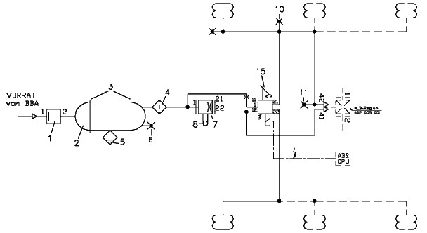
In almost all modern trailer suspensions excellent driving behaviour and good load protection are achieved by a low spring rate of the airbags. The spring rate of the airbags and the spring axle assembly (mechanic stabiliser) form the roll stiffness of the suspension axles, which is important for the roll stability and thus for the safety of the trailer during cornering. The special feature of modern air suspensions is the use of a single air valve, which exhibits a "pseudo-dual circuit air installation". In this dual circuit version with cross restriction in the levelling valve the airbags on the left and right sides of the vehicle are pneumatically separated and only connected by the cross restriction. The airbag of the left and right sides of the vehicle is supplied through connections 21 and 22. During cornering, the air can only equalise itself slowly between the two sides of the vehicle. As a result, the airbags additionally assist in supporting the rolling motion of the vehicle body. Within the air suspension, approx. 80% of the roll stiffness is provided by the spring-axle assembly and approx. 20% by the airbags. Concerning the whole system made up of tyres and air suspension, the share in the roll stiffness of the airbags is only about 10 %, as the spring rate of the tyres has a considerable share in the roll angle of the build-up.
Single-circuit: The right and left sides of the vehicle are directly linked together (no cross-restriction)
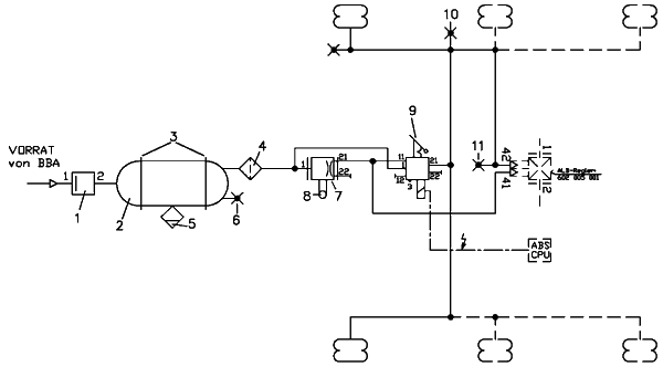
At single-circuit versions without cross restriction, the air bags on the left and right-hand sides of the vehicle are pneumatically connected. There is no transverse flow restrictor. During cornering, the air can equalise itself more quickly between the two sides of the vehicle. This means the rolling motion is not supported by the airbags. The roll stability and, therefore, road safety is reduced in comparison with a dual circuit air installation. As well as the reduction in road safety, the mechanical loads in the air suspension unit are higher. Since there is no roll stabilisation of the airbags, the axle and trailing arm combination has to undertake this portion of the stabilisation as well. The use of single-circuit air suspension installations can lead to damage to the vehicle as a result of the higher loads. For this reason, some axle manufacturers cannot offer any warranty for chassis and suspension damage resulting from this effect. To achieve optimum function and the greatest possible road safety, in particular in critical situations, it is recommended to use dual circuit air suspension installations with a cross restriction. Lifting axles are the only exception to this recommendation. In this case, it is permitted for at most one lifting axle in a three or four-axle unit to be installed with one circuit.
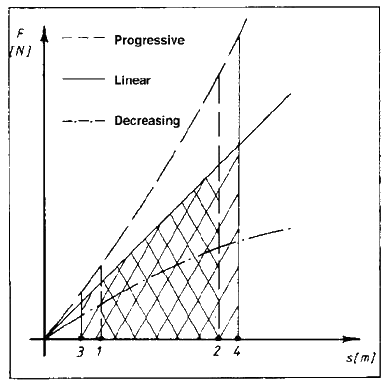
Spring characteristic curve-main diagram (Fig. 1)
Theoretical principles
Definition of air suspension: A suspension system is regarded as air suspension if at least 75% of the spring action is provided by pneumatic devices.
The task of a vehicle suspension is to damp the shocks caused during driving by bumps in the road surface when transmitting them to the vehicle body. This task can be conveniently fulfilled by air suspension. All kinds of air springs are employed as the load-bearing springs for the body load in motor vehicles and trailers. A distinction is made between primary and secondary suspension. The primary suspension carries the weight of the vehicle body permanently, while the secondary suspension only comes into effect in the event of extremely hard road shocks or failure of the primary suspension. The primary and secondary suspensions must be well-tuned to each other, with priority being given to ride comfort in passenger vehicles and to handling (lifting and lowering the vehicle) in goods vehicles. The secondary suspension usually consists of rubber, hollow rubber or plastic springs. Since air suspension possesses almost no intrinsic damping, dampers with higher forces in the tension and compression stages than those for leaf-sprung axles are required.
Furthermore, the air spring bellows can only absorb lateral forces to a limited extent. Consequently, the sprung wheels or axles must be held by links, arms, anti-roll bars and the like.
Spring rates – general
A spring characteristic curve can be linear, progressive or degressive, in which latter case an unstable spring would result. Fig. 1 shows the static and dynamic working range of a spring together with its work capacity, which is shown as the area bounded by the spring characteristic curve, the limits (3) and (4), and the X-axis. The dynamic working range overlaps the static, depending on the available dynamic spring travel (paths 1 – 3 and 2- 4).
Important: The total spring deflection therefore consists of the static spring travel, which occurs when the vehicle is loaded while at rest, and the dynamic spring travel, which is the same as the bottoming travel. The smaller the spring rate and the larger the (vehicle) mass, the smaller the (body) acceleration and the better the ride comfort is.
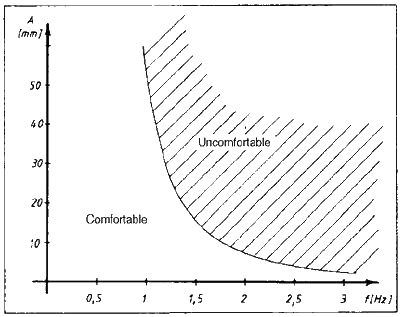
Ride comfort (Fig. 2)
The following conclusions can now be drawn:
- to obtain a high degree of ride comfort at all times, the ratio of axle spring constant to body weight must remain the same.
- The natural frequency of the body must be as small as possible if good ride comfort is to be achieved.
- The natural frequency can be influenced by both the spring rate and the body mass.
- The natural frequency has a very great effect on ride comfort. Since ride comfort is very difficult to represent objectively, subjective perceptions must be employed to describe the comfort mathematically or graphically. It can be seen clearly that the zone experienced by people as comfortable not only presupposes a relatively very small natural frequency but also depends on the vibration amplitude.
- If the natural frequency is to be kept as constant as possible under varying loads, the spring rate must be changed in such a way that the ratio of spring rate to weight remains constant. The increasing importance of lightweight construction and the associated large difference in weight between an empty and a loaded vehicle make the need for a controllable spring ever more urgent.
Compressed air generation and storage
For safety reasons, the compressed air for the braking system must be kept separate and isolated from that of the air suspension. Circuit 1 and 2 (connections 21 and 22 on the quadruple-circuit protection valve) is always allocated to the SB.
On air suspension systems for trailers or semi-trailers, the pressure level corresponds to that of the braking system, since the air suspension system is supplied from the braking system supply line.
Various systems can be differentiated in tractor units:
- pressure in the air suspension system = pressure in the braking system (corresponds to trailer/semi-trailer).
- pressure in the air suspension system is greater or smaller than the pressure in the braking system (trucks and buses).
- In the first instance, the compressed air for the air suspension is taken from the ancillary consumer circuit (connection 23 or 24 on the quadruple-circuit protection valve) after the quadruple-circuit protection valve, in which case the quadruple-circuit protection valve must be designed to give priority to filling brake circuits 21 and 22 (legal requirements as from 1st October 1994). In most instances, the air suspension system is provided with a higher pressure than the braking system. Here, the compressed air is taken between the governor valve and the quadruple-circuit protection valve, and fed to the air suspension air tank through a pressure protection valve with limited backflow (or no backflow at all) set to a higher pressure than the quadruple-circuit protection valve. This kind of design has the advantage that smaller air spring support bellows and air tanks can be installed. It also allows shorter filling and exhausting times, since the pressure difference between the storage tank and the air spring support bellows is greater.
- On trailer vehicles, the supply for the air suspension is taken from the service brake supply. Both circuits must be isolated from each other by a pressure protection valve (with or without limited backflow). The opening pressure is about 6 bar, since the isolating pressure is laid down by law as at least 5.2 bar.
LSV load sensing/EBS control
One major advantage of air suspension is that the bellows pressure, which depends on the load condition at any given instant, can be used to control the automatic load-dependent load-sensing valve/EBS. A function of this kind shows in the figure on the top for the dual-circuit air suspension, when using a twin-circuit automatically-controlled load sensing valve, the intact bellows still ensure load-dependent control of the braking pressure, even in the event of a line breakage.
Depending on the design, an adequate braking effect can still be obtained in vehicles with full or partial air suspension in the event of faults in the air suspension system.
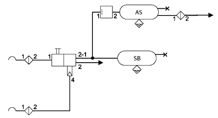
Air supply example (Fig. 3)
AS = Air suspension
SB = Service Brake