Aux to Aux
Aquí encontrará una descripción ampliada, vistas de los conectores y ayuda para el diagnóstico.
- To connect the Aux splitter (814 039 101) to ECU auxiliary socket
- Conforms to IP67 when mated with ECU auxiliary connector.
- Cable insulation material : PVC
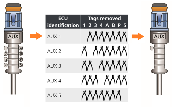
- Use tag to identify auxiliary position :
Identification tags are incorporated on either side of the auxiliary connector. These must be removed to identify the appropriate usage before connecting into the ECU.
AUX plug
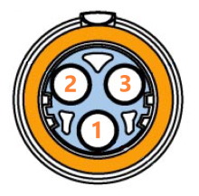
| Pin | Description | Color | Section (mm2) |
|---|---|---|---|
| 1 | Output | Red | 0.75 |
| 2 |
B- |
Black | 0.75 |
| 3 |
Input (Output only possible with Premium Gen3) |
Yellow | 0.75 |
Diagnostic
The Auxiliary cable can have multiple applications. It can be used for an output (ILAS-E, COLAS, ...) or for an input (Pressure sensor , switch, ...)
Depending the use, Input or Output, the voltage and the way to check is changing
| OUTPUT AUX | ||||
|---|---|---|---|---|
| Test points | Condition | Required value | Measured value | Comments |
|
1 - 2 Red - Black
Only for Gen3 Twin AUX : 3 - 2 Yellow - Black |
Output is ON |
B+ |
If the measured value is below B+, it can indicate a resistance in the wiring. Next steps :
|
|
|
1 - 2 Red - Black
Only for Gen3 Twin AUX : 3 - 2 Yellow - Black |
Output is OFF |
5V (detection voltage) |
The ECU use this low voltage to determine if a load (solenoid) is connected or not. Next steps :
|
|
| INPUT AUX | ||||
|---|---|---|---|---|
| Test points | Condition | Required value | Mesured value | Comments |
|
1 - 2 Red - Black |
Power ON |
5V |
Never connect the black wire to the vehicle's ground ! This 5V must only be used for a switch or sensor power Next steps :
|
|
|
3 - 2 Yellow - Black |
- |
Input signal |
In general, switching voltage is 0V to 5V analogic (sensor), up to B+ (switch) For General Purpose Input use, the switching voltage depends of the configuration, and need to be checked in ECU setup Next steps :
|
|