Standard EGP
The standard EGP levelling valve offers a simple way to achieve a constant chassis height.
Installation
The levelling valve has to be installed vertically with an exhaust port at the bottom. For fixing use at least two M8 screws. The tightening torque for fixing the body is 20+2 Nm. Where only one valve per bogie is used the valve must be located in the area of the middle of the axle. The freedom of movement of the centre axle has to be checked. The linkages must be installed distortion-free.
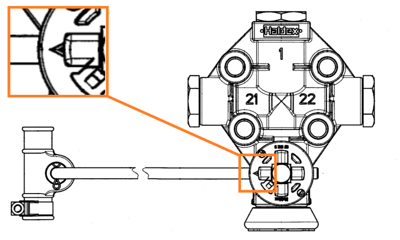
Attention: The arrow marker indicates the installation direction of the linkage!
On valves with push-in fittings use only nylon pipes 8x1 following DIN 74 324 or 1/4" x 0,04 following SAE J844. When assembling the nylon pipes, care should be taken to ensure that the pipes are cut square, to the required length and are free from burrs. Before inserting the pipes in the push-in fittings don´t support sleeves in the ends of the pipes if there are brass fittings. On brass fittings, the sleeves are integrated inside the ports. On ports with plastic-type push-in fittings, you have to insert sleeves, e.g. following HALDEX order number 032 049 009 in the ends of the pipes. Pipes are to be inserted at least 18.5 mm deep in the connections.
On valves with threaded ports fix the fittings to the respective torque.
- Tightening torque ports (thread M 12x1.5): 12 - 15 Nm.
- Tightening torque ports (thread M 16x1.5): 20 - 25 Nm
In the event of paint/coating work all open connections including the exhaust port should be protected by suitable means to avoid penetration of the paint/coating. After painting/coating remove this protecting material. In the supply coming from the air reservoir a line filter should be installed (to guard against pollutants).
Inspection
- Test for operation and leaks.
- The pressure should neither rise nor fall at the delivery ports in the neutral position.
- Check the linkage moves freely and is in good condition, replace if bent or welded.
- Replace hardened or brittle rubber parts
Maintenance
- If defects are noted during vehicle examinations or when driving, then the unit should be exchanged.
- When working with high pressure cleaners a distance of at least 50 cm should be observed.
- Missing exhaust caps are to be renewed.
Technical data
| Medium | Air |
| Operating pressure, dynamic | 13 bar |
| Max. permissible bellow pressure | 20 bar |
| Working range (charging / discharging) | 45° |
| Thermal range of application | - 45° ... + 85°C |
| Operating side | left and right |
| Tightening torque ports (thread M12x1.5) | 12 - 15 Nm |
| Tightening torque for fixing the body | 20 - 22 Nm |
| Tightening torque for fixing the linkage (wrench size 10) | 8 Nm |
| By rotating the linkage around 180° the same function will be achieved within a tolerance | 3.5° |
| Dead angle at p1 = 8 bar, p2 = 7 bar | 2° |
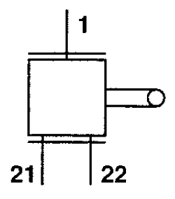
| Ports 1 |
Supply |
| Ports 21, 22 |
Delivery |
| Port 3 | Exhaust |
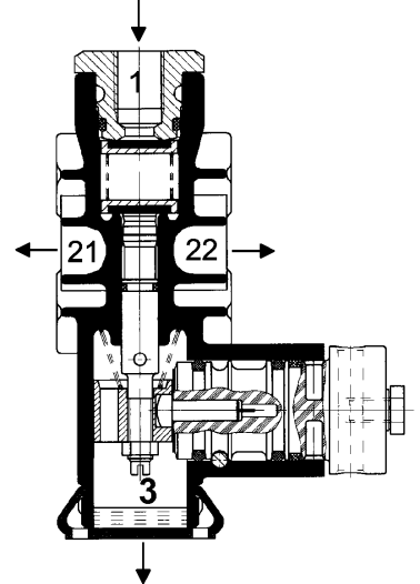
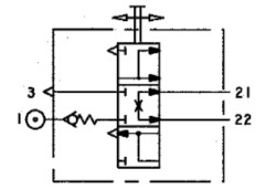
Sectional drawing
|
1 - Reservoir 21,22 - Suspension 3 - Exhaust |
 |
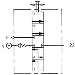
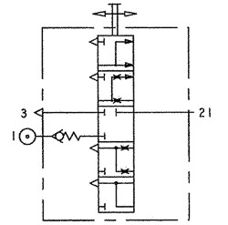
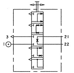
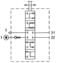
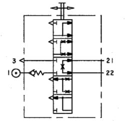
Symbol
Symbols show the internal function of the levelling valve, with restrictions inside, the reaction will be progressive (increase lateral stability for road vehicle), whereas without restrictions the time to inflate the bellows will be shorter (container trailer, tipper), see also the type charts below.
| DIN ISO 1219 | ||
|---|---|---|
| Symbol 1 | Symbol 2 | Symbol 3 |
|
|
|
 |
|
|
|
|
| Symbol 4 | Symbol 5 | Symbol 6 |
 |
 |
 |
| DIN 74253 |
|---|
|
|
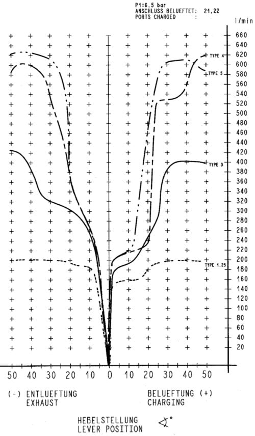
Type chart (flow)
The Type chart shows the airflow depending on the angle of the lever. The higher the type number is (internal diameter of the valve) the higher the air flow rate is reached. The curve profile is also important, as they are more or less progressive in the range 0° to 20° angle.