Installation
The pressure protection valve is normally installed directly into the vehicle reservoir using an M22 bulkhead connector (vehicle piping diagram required before installation). The air flow direction from 1 to 2 (see arrow on valve) must be observed.
Port 1 IN from reservoir
Port 2 OUT to auxiliary
Testing
- Check for correct function and air leaks
- Check opening and closing pressures with test gauges. In the port 1 and/or 2 the pressures must be in according to the index versions and data of the vehicle manufacturer
- Leak-tightness check
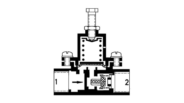
Charge position
Air flows through port 1 and pressurizes the underside of the diaphragm. After reaching the adjusted opening pressure, the diaphragm moves off its seat and air flows through port 2 and thus to the auxiliary circuit. On the valve without back flow in addition the before port 2 located check valve is opened.
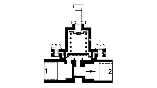
Protect position
At a relatively large drop in pressure at port 2, e.g. a defect in the auxiliary circuit, air from port 1 flows into port 2, until the spring presses the diaphragm onto its sealing seat. In port 1 the protected pressure remains.
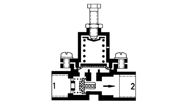
Back flow position
In the back flow position in port 2, the pressure indicated in the index remains.
1. Valve without back flow C :A drop in pressure at port 1 the check valve closes, resulting in no back flow from 2 to 1.
2. Valve with back flow A : A drop in pressure at port 1 the check valve opens, whereby air from port 2 can flow to port 1.
3. Valve with limited back flow B : A drop in pressure at port 1, air flows from 2 to 1, until the power of the spring overcomes the pressure beneath the diaphragm, sealing the protected pressure in port 2. If a defect occurs in port 2 (ventilation to 0 bar) protected pressure must remain in port 1 (on all versions).
Valve without back flow C: 314 012 ...
Valve with back flow A: 314 013
Valve with limited back flow B: 314 014 ...