Installation
- The TrCM+ is fixed to the vehicle chassis with two/three M 8 bolts.
- The control knobs must be easily accessible.
- Not used ports must be plugged.
- For painting/coating all open ports must be protected to avoid penetration of the paint/coat.
- For fittings / push-in fittings refer to the instructions of the respective manufacturer.
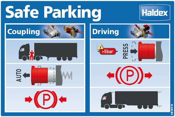
Function
Valve |
Black knob (shunt valve) |
Red knob (park valve) |
Trailer coupled |
Operation Conditions |
Service brake system |
Park brake
|
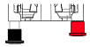 |
pulled | pushed (must be manually pushed) | yes | Drive | released | released |
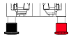 |
pulled | automatic pulled out | no | Trailer uncoupled/braked | Emergency function engaged | Safety function: Released via overload protection valve |
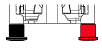 |
pushed | pushed | no | Shunting | released | released |
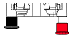 |
pushed | pulled | no | Parking (uncoupled) | released | engaged |
|
pulled | pulled | yes | Parking (coupled) | released | engaged |
Warning - Danger! Before starting the journey, the spring brake cylinder must be released manually by pushing the park valve.
Inspection
- System without pressure
Shunt valve (black button) must be pushed in (securing the trailer vehicle previous to this test), park valve (red button) automatically pushed out. - Initial charging
Apply pressure to port 1; the shunt valve (black button) must go into the operating position (jump out). The park valve (red button) remains pushed out. - Automatic emergency braking
Lower the pressure at Port 1 to 0 bar; the port 21 emergency braking must activate automatically. - Pressure protection valve
Instructions for adjustment may be found in the fitting instructions, order no.: 000 314 012. - Park brake valve (red button)
Apply pressure to port 1. park valve (red button) automatically pushed out, push the park valve (red button) in, at least 5.0 bar in the supply reservoir, pull the park valve (red button), port 2 (spring brake system) must vent down to 0 bar, vehicle braked.