DIAGN/CAN to DIAGN/CAN
Find here extended description, connector views, and help for diagnostic as well !
Description
To connect an EB+Infocentre to the ECU DIAGN/CAN socket.
- To connect DIAGN splitter to the ECU DIAGN/CAN socket
- Conforms to IP67 when mated with ECU and Infocentre or DIAGN/CAN splitter
- Cable insulation material: PVC
DIAGN/CAN plug
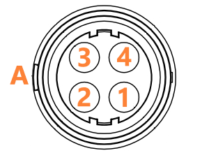
| Pin | Description | Color | Section (mm2) |
|---|---|---|---|
| 1 | B+ | Red | 0.75 |
| 2 | CAN High | Green | 0.75 |
| 3 | CAN Low | Yellow | 0.75 |
| 4 | B- | Blue | 0.75 |
"A" indicate the clip side
Diagnostic - ISO11898
The Haldex Can bus uses 4 wires, 2 are for power supply, 2 for the communication (CAN High and CAN Low)
It can be used for ECU extensions, diagnostic or telematic.
Before to start the checking's, be sure you know the CAN bus layout of the vehicle. Depending on the ECUs mounted, you could find splitters and extension cables to link all the network together.
In practice, always start to check the CAN bus from one end to main ECU (EB+ or U-ABS), then check again the different cable or splitters separately.
| Test points | Condition | Required value | Measured value | Comments |
|---|---|---|---|---|
| 1 / 4 | Power ON | B+ |
If the measured value is below B+, it can indicate a resistance in the wiring Next steps :
|
|
| 2 / 4 | Power ON |
0V < V < 5V |
The average voltage of CAN High wire is around 2.5V Next steps :
|
|
| 3 / 4 | Power ON | 0V < V < 5V |
The average voltage of CAN Low wire is around 2.5V Next steps :
|