U-ABS Power-A splitter
Find here extended description, connector views, and help for diagnostic as well !
- For Roadtrain or multiple U-ABS installation
- Unit must be positionned to give maximum protection from projectiles
- Conforms to IP67 when mated with Power-A plugs
- Temperature range : -40°C to 80°C
- Connections not to face upwards
- See installation manual 006 300 022
- If screwed fixing is utilised then use M6 fastener and tighten 4.5 - 6.1Nm
Power-A socket
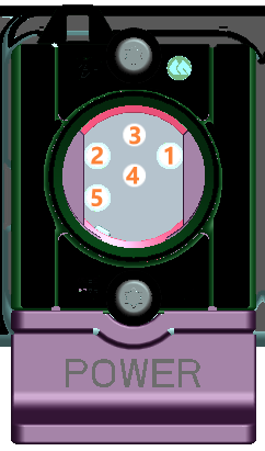
| Pin | Description |
|---|---|
| 1 | B+ Permanent |
| 2 | B+ Ignition |
| 3 | B- Ignition |
| 4 | B- Permanent |
| 5 | Lamp return |
Diagnostic
Diagnostic ISO 7638 ABS/EBS
ISO7638 connection is the mandatory power supply for ABS/EBS systems. If the system is showing a wrong function, the power supply must be the first step of the diagnostic!
Before to use the table below, first check the reaction of the system at power ON, either with service brake applied (Brake pedal) or with the red coupling head disconnected (Emergency braking mode) or with the yellow line supplied (At 6.5 bar air pressure).
When switching power ON
- Each modulator exhausts one time (the number of exhausts must be the same as the number of modulators).
- ABS warning lamp on dashboard indicates a specific sequence (ON/OFF) or (ON/OFF/ON)
If not, check power supply :
|
Test points (with 21W lamp) |
Condition | Required value | Measured value | Comments |
|---|---|---|---|---|
|
Power-A plug 1 - 4 |
ISO7638 connected Switch power OFF |
B+ |
If permanent power is missing (0V), solenoids are not powered. If measured value is below B+ (voltage drop), it can indicate a resistance in the wiring. Next steps :
|
|
|
Power-A plug 2 - 3 |
ISO7638 connected Switch power OFF |
0V |
A permanent power indicates a wrong wiring or short circuit. Next steps :
|
|
|
Power-A plug 2 - 3 |
ISO7638 connected Switch power ON |
B+ |
If switch power is missing, ECU is not powered. If measured value is below B+ (voltage drop), it can indicate a resistance in the wiring. Next steps :
|